| Digital Audio |
| NEW! Dual Zo Digital Audio |
| Custom & HV |
| Catalog |
| FAQ's |
| RoHS Lead Free FAQ |
| Latest News |
| About Us |
| Contacts |
| 1998 AES Paper |
| 2001 AES Paper |
| 2003 AES Paper |
| Sales |

| Characterizing Digital Audio Transformers with Induced Jitter Histograms
Presented at the Audio Engineering Society Convention, New York December 2001 By Jon D. Paul, Vice President |
|
  |
|
|
ABSTRACT Transformers are employed in digital audio systems primarily to reject common mode noise interference. A new test characterizes the interference rejection of a practical transmission system with a transformer at the receiver input. A sample set of the decoded frame sync clocks are accumulated by a statistical time interval analyzer. The analyzer calculates the mean value of the periods, the standard deviation (jitter), and provides a period histogram. The histogram and standard deviation establish a basis for comparing the high frequency interference rejection of various transformers and for quantifying the nature of the induced jitter. Test data are presented for 7 different types of transformers. |
|
|
Figures Fig. 1
Transformer Coupled Digital Audio Transmission System Fig. 2
Common-Mode Noise Rejection Fig. 3 Effect of Different transformers on CM noise
Fig 5 Test Fixture Photo Fig 6 Time Interval Analyzer Fig. 7 Relationship of observed jitter to system component jitter Fig. 8 Induced Common-Mode Noise Jitter Comparison Fig. 9 Typical AES/EBU transformers Fig. 10
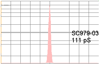
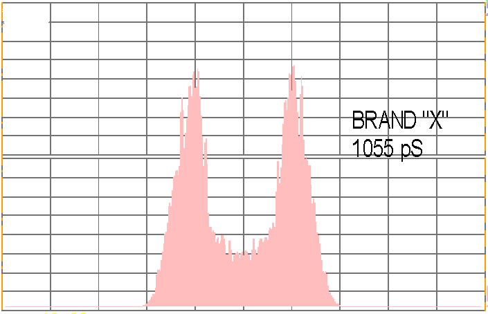
- Fig. 18 Jitter Histograms of Various Transformers Fig. 19 Correlation of Various Transformer Parameters vs Jitter Fig. 20 Jt Vs Cps Fig. 21
Comparison of 7 AES Transformers Summary and Conclusions
•
Induced Interference Testing simulates field conditions
•
Commercial transformers exhibit tremendous differences in interference rejection
•
AES/EBU receivers exhibit jitter that is function of the transformer CMRR and capacitance
•
Professional, broadcast and high resolution applications need maximum CMRR to minimize recovered clock jitter in the presence of noise.
|
|
|
NOTE: If the papers don't load completely, save the PDF file to your disk; open with Acrobat Reader 7. Copyright © 2002 Scientific Conversion, Inc. All rights reserved. Information in document is subject to change without notice.
|
|
All material on this website is Copyrighted, use without permission is prohibited.
