|
| |

 |
|
The Effect of Transformers on Transmission of Digital Audio Signals
Presented at the Audio Engineering Society International Convention, San Francisco, 1998
By Jon D. Paul, Vice President
Scientific Conversion, Inc.
California, USA
|
|
|
|
Index
1. Transformers in Digital Audio Transmission Systems
2. AES/EBU Signal Bandwidth
3. Transformer Equivalent Circuit
4. Frequency Response and Saturation Effects
5. Pulse Aberration
6. Common-Mode Rejection Ratio and Interference Suppression
7. Common-Mode Interference: Induced Jitter Test
8. Common-Mode Interference: Induced Jitter Results
9. Transmission System with Shielded Transformers
10. Typical Digital Audio Transformer Applications
10.0 Balanced 110 W System with Shielded Transformers
10.1 75 W Unbalanced Interface with 2:1 Ratio Transformers
10.2 Bridging Unbalanced Input and Floating Coax Connector
10.3 Phantom Power Remote Digital Device
10.4 Dual output transmitter, 110 W Balanced and 75 W Unbalanced
11. Comparison of Typical Transformers
12. PC Layout Considerations
|
|
 |
|
Figures
Fig. 1 Direct Coupled Transmission System
Fig. 2 Transformer Coupled Digital Audio Transmission System
Fig. 3 Spectrum of Digital Audio Signal 10kHz/div
Fig. 4 Spectrum of Digital Audio Signal 5MHz/div
Fig. 5 Equivalent Circuit of Transformer
Fig. 6 Frequency Response of Transformer
Fig. 7 Frequency Response of Transformer
Fig. 8 Effect of Transformer High-Freq. Bandwidth on Pulse Resp.
Fig. 9 Effect of Transformer Low-Frequency Bandwidth on Eye Pattern
Fig. 10 Effect of Core Saturation on Waveform
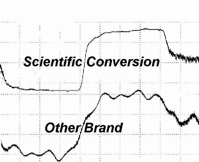
Fig. 11 Comparison of Pulse Aberration Squarewave Gen. 12.288 MHz, 75 W in/out
Fig. 11A Comparison of Aberration Received AES/EBU 31M UTP 96kHz FS, 110 W in/out
Fig. 12 Common-Mode Noise Rejection Test Circuit
Fig. 13 Common-Mode Noise Rejection
Fig. 14 CS8412/48kHz Common-Mode Noise Induced Jitter Setup
Fig. 14 HP 5370B Time Interval Counter
Fig. 14A 96kHz Common-Mode Noise CS8404A/CS8414/96kHz Jitter
Fig. 14A Yokogawa TA320 Time Interval Analyzer
Fig. 14B no transformer. RMS jitter 3401ps
Fig. 14C type "B" RMS jitter 1540ps
Fig. 14D type "V" RMS jitter 906ps
Fig. 14E type "H" RMS jitter 396ps
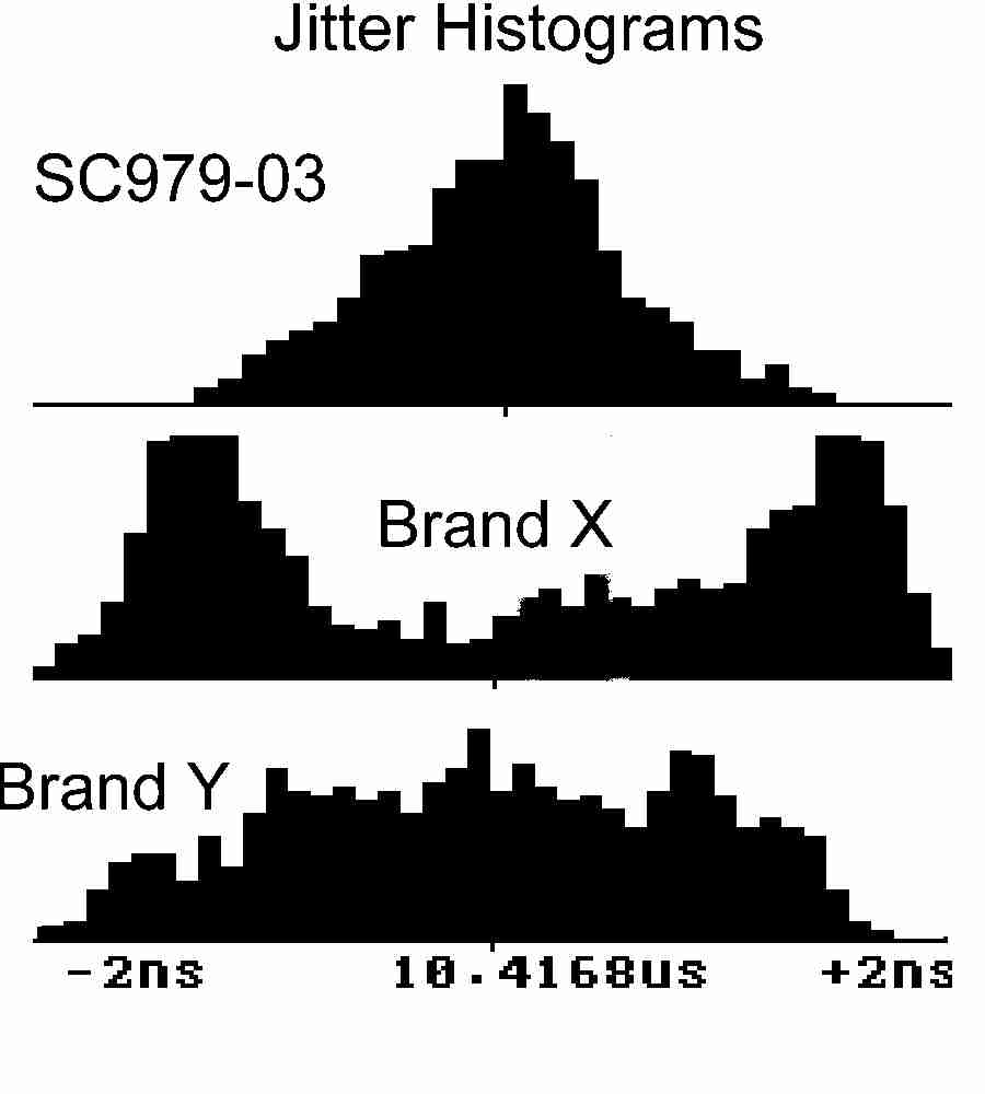
Fig. 15 Induced Common-Mode Noise Jitter Comparison
Fig. 16 Shielded Transformer in Common-Mode Noise Equivalent Circuit
Fig. 17 Balanced Transmission System Using Shielded Transformers
Fig. 18 Application of 2:1 Transformers to 75 W Unbalanced System
Fig. 19 Hi-Z Bridging Unbalanced Input with Floating Coax Connector
Fig. 20 Phantom Power to Remote Digital Device
Fig. 21 Dual Output Transmitter, both 110 W Bal and 75 W Unbal
Fig. 22 Comparison of Transformers
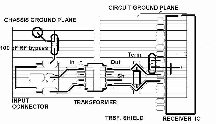
Fig. 23 Suggested PCB Layout for Transformer Input Circuit
|
|
|
|
Commercial transformers exhibit tremendous differences in parameters and performance. Digital audio transformers substantially improve common mode noise rejection and EMI emission. Second order effects such as pulse aberration and saturation greatly influence waveform fidelity. AES/EBU receivers exhibit jitter that is a function of the transformer CMRR and capacitance. Professional, broadcast and high resolution applications need maximum CMRR to minimize recovered clock jitter in the presence of noise. High quality transformers offer cost effective improvements in product design.
NOTE: If the papers don't load completely, save the PDF file to your disk; open with Acrobat Reader 7.
You can download and upgrade your Acrobat Reader here
Copyright © 2008 Scientific Conversion, Inc. All rights reserved. Information in this document is subject to change without notice.
- THE BEST TRANSFORMERS IN THE INDUSTRY!

- Last revised:
8 March 2008
|
|